Prototype 2
This is Klevor's second version, in which we made essential correction and added new components.
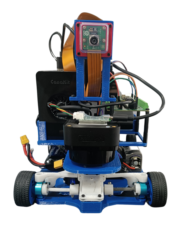 Front View
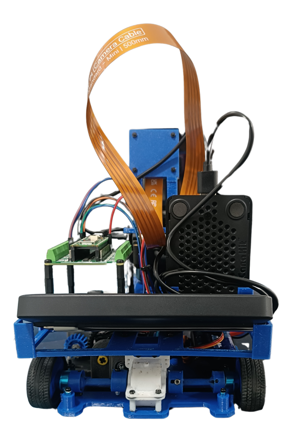 Back View
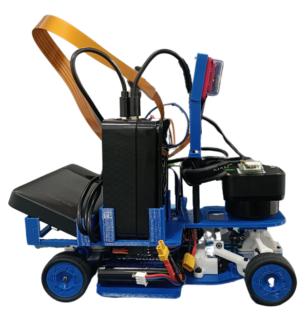 VRight View
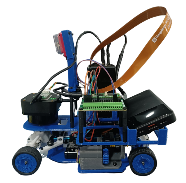 Left View
 Top View
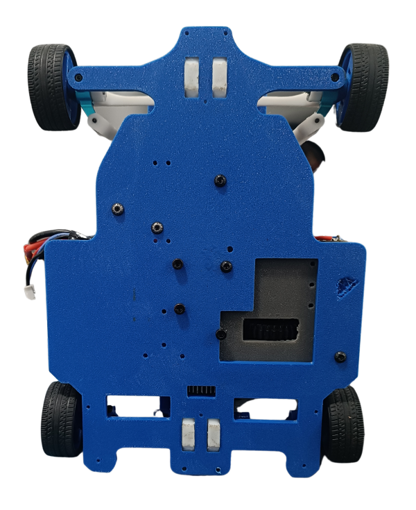 Bottom View
First Layer
In the first layer, like our first prototype, we have our drive system, which recieved some modifications. works like a drive system of a car, a 4x4 mechanism with two differentials (a gear system covered in a casing)connected with a transmission shaft. We connect our motor (INJORA 48T) to the transmission's shaft pinion, this moves the differentials in the same direction, and, moves Klevor.
Another fundamental part for our robot is its crossing system, which consists of a servomotor (INJORA 7 kg 2065) which is connected to our "Ackermann" system that works by connecting both wheels to a steering or "trapezoid system". The servomotor moves some bars that are connected to the steering knuckles, thus allowing that one of the steering knuckles to be pushed to one side by the movement of the servomotor and in turn, pull the other wheel to the other side. Due to the angles of the trapezoid, this causes that the interior wheel to turn more than the outer one.
To operate, the wheels are connected to a steering knuckle, then to a "shaft" or "half-shaft" that passes through the knuckle and joins the wheel so that it turns; the shaft turns while it is next to the differential.
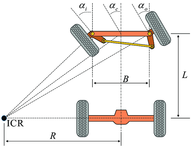 Ackermann System
This diagram provides a clearer example on how this system works. We'll describe the meaning of each term below:
-
ICR (Instantaneous Center of Rotation): It's the point around which the front axle is rotating.
-
R: It's the vehicle's turning radius, measured from the ICR to the center of the rear axle.
-
L: It's the distance between the front and rear axle, or, the transmission shaft's length.
-
B: It's the distance between the sterring knuckles (The piece on which the wheel goes and is connected to the steering).
-
a(i): Is the turning angle of our inner wheel compared to the curve.
-
a(o): Is the angle of our outer wheel with respect to the turn.
This ilustrates better the steering geometry that allows for the front wheels to turn in different angles and, at the same time, achieving a more efficient turning.
The electronical components included in this layer are: the gyroscope (BNO08X) which helps the robot orientate itself and count the number of turns it has done, a battery (URGENEX 7.4 V), which powers the INJORA MB100 20 A mini ESC which is an Electronic Speed Control, this ESC powers the motor INJORA 48T and the servomotor INJORA 7 kg 2065.
Why did we design our chassis this way?
This chassis is a direct modification from the first layer of the firsst Klevor prototype. We decided to modify it due to weight limitations, reducing space for removed components, this first layer is also designed with non-modifiable parts, like the differentials, steering knuckles and the transmission shaft. So customized the layer to fit each components exactly. This is why we also designed the entire connection part of the wheels (Wheels, semi-shafts and gearboxes).
Second Layer
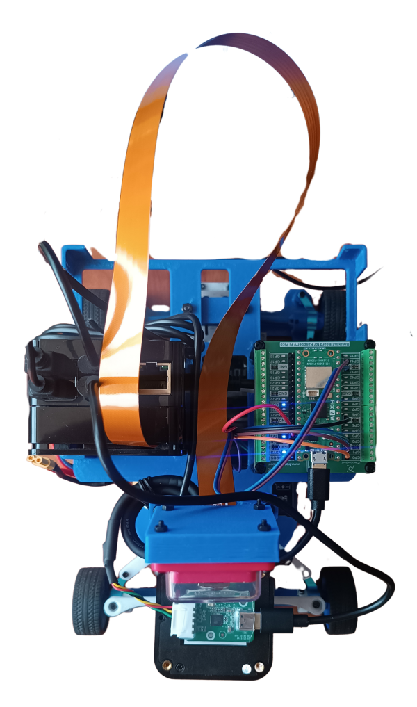
This is the layer that we modified the most, previously we had the ToF (Time of Flight) sensors, which were replaced by the RPLiDAR C1 a 360 degree laser scanner sensor that has a range of up to 12 meters, which corrects the malfunction of previous ToF sensors (Time of Flight), which returned wrong values and had a lower detection range. We decided to use it upside down to avoid the laser being over the game field's walls.
In this upper layer we can also find the microcontroller (Raspberry Pi Pico 2 WH), and the microprocesser (Raspberry Pi 5), as well as their power supply which is a Harvic Power Bank with 10000 mAh capacity and 22.5W output, this is connected to the Raspberry Pi 5 and, at the same time, powers the RPLiDAR C1; the Raspberry Pi Pico 2 WH and the Raspberry Camera Module 3 Wide which is the key aspect to help Klevor solve the Closed Challenge.
Why did we design the upper layer this way?
The upper layer changed drastically in comparison to the previous prototype, the changes we did are as follows:
-
Create a gap in the front: This adjustment was made so that the RPLiDAR C1 had a bit more range.
-
Cut corners: Kind of self-explanatory, our main goal was to reduce unnecessary weight and space
-
Add holes: Again, pretty simple change, the main objective was so free up some space to connect cables for the lower layer's components, making the assembling process easier.
-
Raspberry Pi Camera 3 Mount: After testing out which angle worked best for the camera, we decided to fix the camera mount to said angle. However this mount can be replaced soon.
We decided to also delete the third layer that the first prototype, because we could fit everything into just two layers.
Bill of Materials
| Component | Unit | Cost per Unit ($) | Total ($) |
|---|---|---|---|
| Raspberry Pi 5 | 1 | 120.00 | 120.00 |
| Raspberry Pi AI HAT+ | 1 | 139.95 | 139.95 |
| Micro SD 512GB | 1 | 54.99 | 54.99 |
| RPLiDAR C1 | 1 | 75.90 | 75.90 |
| Raspberry Pi Pico 2WH | 1 | 14.99 | 14.99 |
| Raspberry Pi Pico 2WH Breakout Board | 1 | 11.95 | 11.95 |
| Raspberry Pi Camera Module 3 Wide | 1 | 37.95 | 37.95 |
| Case para la Raspberry Pi Camera Module 3 | 1 | 5.99 | 5.99 |
| Cable para la cámara de la Raspberry Pi 5 de 50cm | 1 | 9.79 | 9.79 |
| URGENEX 3000mAh Battery | 1 | 26.99 | 26.99 |
| Giroscopio BNO085 | 1 | 18.59 | 18.59 |
| INJORA 7Kg 2065 Servo | 1 | 17.98 | 17.98 |
| INJORA MB100 20A Brushed Mini ESC | 1 | 32.99 | 32.99 |
| INJORA 180 48T Motor PRO | 1 | 13.98 | 13.98 |
| Harvic Power Bank PB-607 | 1 | 17.50 [1] | 17.50 [1] |
| Aluminium Alloy Front & Rear Steering Knuckle Hub Base | 1 | 17.99 | 17.99 |
| RC Car Metal Differential Kit 1/18 | 1 | 21.98 | 21.98 |
| 10PCS Toy Car Wheels 35mm | 1 | 7.99 | 7.99 |
| 20 Ball Bearings MR128-2RS | 1 | 9.29 | 9.29 |
Total Component Cost: $656.79