Current Common Parts
RPM Reductor System
 RPM Reduction System
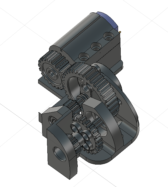
In this 3D model we can visualize how this system is designed. We will proceed to show and explain each of the parts' purposes.
System Mounting
 RPM Reductor System Mounting
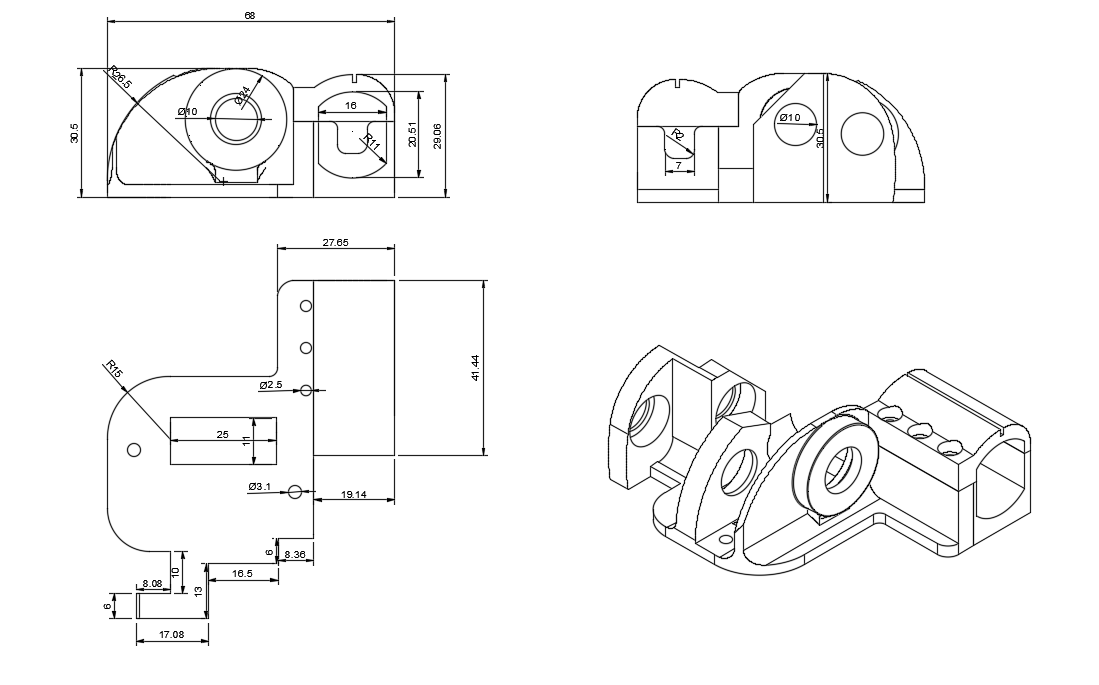
This is where all of the system's components are mounted on. It's designed to be as efficient with the space as possible without having to risk any of the functionality.
Pinions
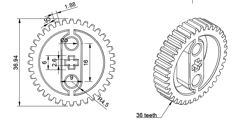 36-tooth pinion
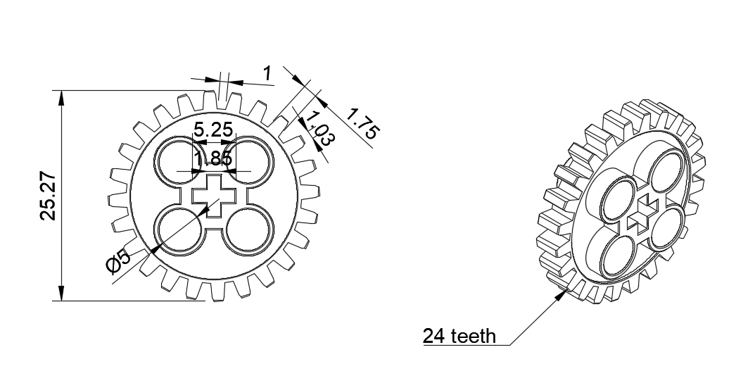 24-tooth pinion
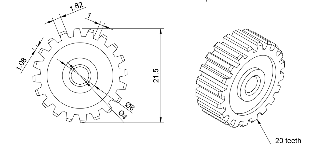 20-tooth pinion
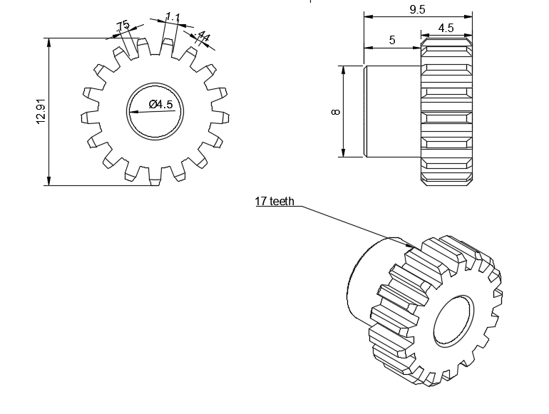 17-tooth metal pinion
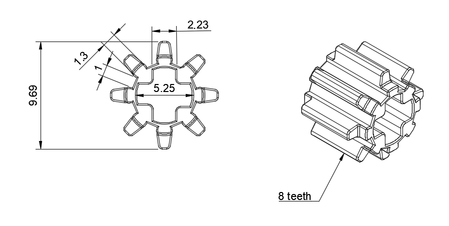 8-tooth pinion
These are the system's most important components, basically, it slows the engine down, but increases the actuators' torque, making sure it's enough torque to be able to move Klevor. These gears are leftovers from other kits, so we used them so they wouldn't go to waste.
System Shaft
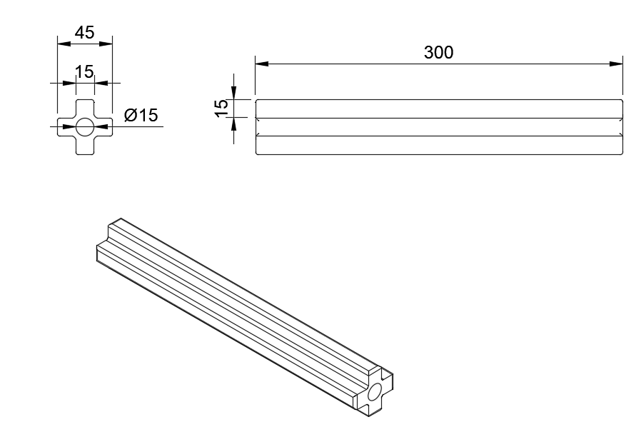 RPM Reduction System Shaft
We used two shafts for this system, their main purpose is to simply hold the pinions and keep them at a fixed and stable height. Thanks to its incredible resistance, this part allows that the gears are aligned accurately.
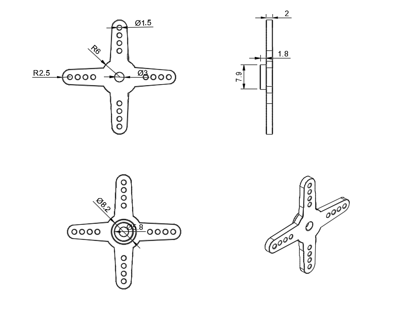
Separators
 RPM Reduction System Separator
These are another resource we used to keep the gears in a fixed position, to further secure this system's functioning. This is also another reused piece. We used three units.
Bushings
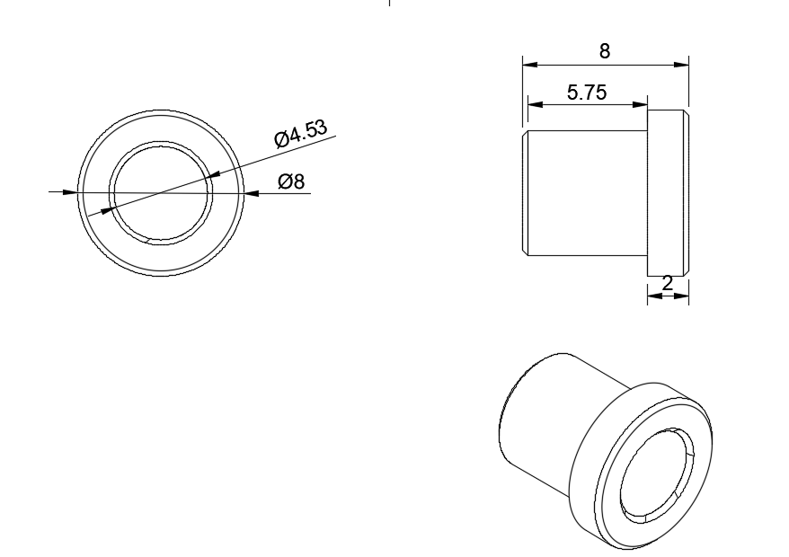
The bushings play a very crucial role in this system, these are in charge of holding firmly the shafts, while allowing the free and efficient spin from the gears.
Servomotor
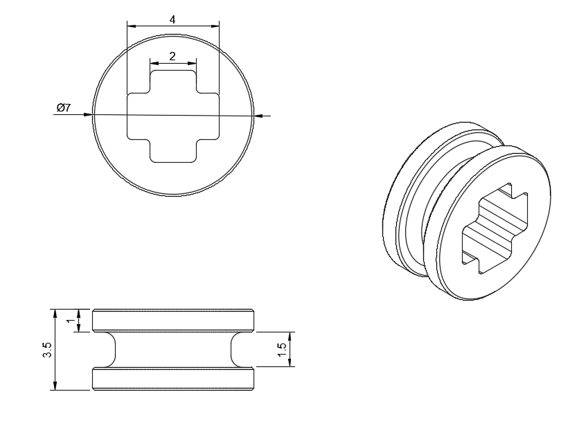
Cross-shaped Separator
 Cross-shaped Separator
This part is connected directly with the bushing just below the 36-tooth pinion. We take advantage of its design, which allows it to fit either the hub or one of the shafts, ensuring precise alignment. The entire system is designed so that the parts snap together, ensuring a firm connection.
What is this system's purpose?
This system is designed to convert thye INJORA 48T motor's high speed (20,000 RPM) but low torque into a movement that is slower but with higher torque. The system starts with the 20-tooth pinion on the motor shaft, which moves a 36-tooth gear. Which is also, mounted on the main system shaft with the 8-tooth pinion with moves the 24-tooth pinion. Finally, a 17-toth pinion moves the 40-tooth gear which is connected to the transmission axle. Each gear provides a reduction, and when combined, we get a total relation of about 1:12.69, what this means is that, for every 12.69 spins the motor does, the transmission axle gear spins one time. This design allows the robot to increases the push and pull force, sacrificing speed in favor of more force.
Drive System
Differential
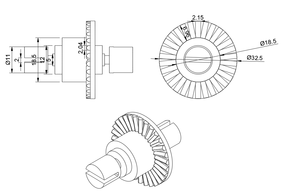 Differential
The entirety of the drive system is based on the use of two differentials, which play a fundamental role in providing traction to all four wheels. Thanks to this configuration achieves perfect power distribution.
Gearbox
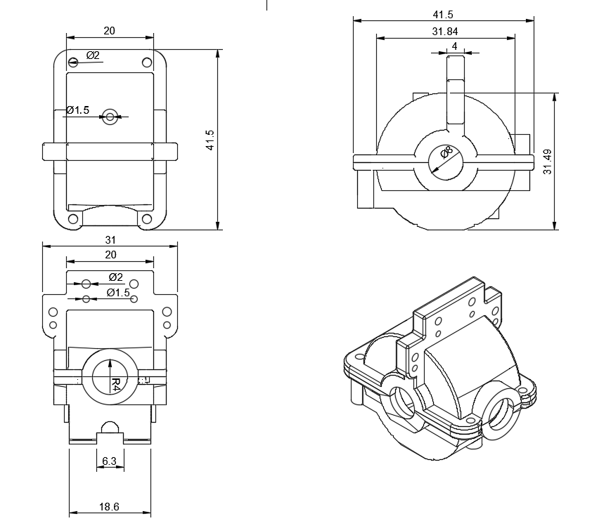 Gearbox
This is the differential is mounted on, protecting it and holding it in place. The components that allow the wheel to rotate also extend from this point. Its design ensures the differential's stability and proper operation.
Transmission Shaft
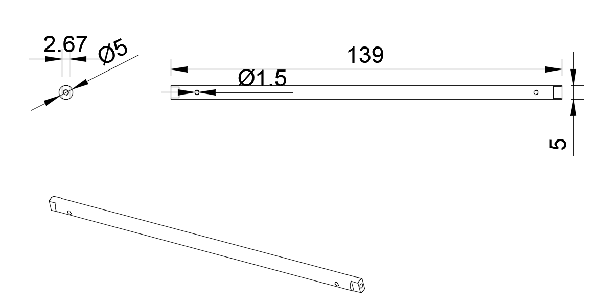 Transmission Shaft
This part serves the key function of connecting both differentials, allowing them to synchronize. This connection assures that the robot's four wheels move evenly, distribute torque evenly.
Transimssion Cup
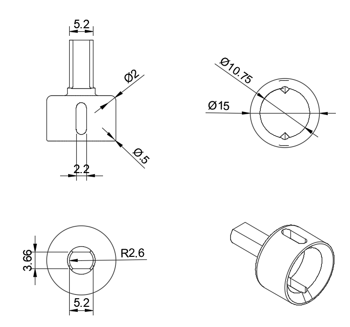 Transmission Cup
We use this part specifically for the differential. It's precision-enginereed to fit perfectly with the axle shaft, allowing the wheels to efficiently recieve movement.
Back Knuckle
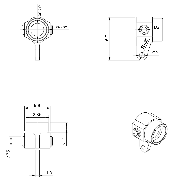 Back Knuckle
This part supports the wheel, serving the connection point between it and the drive system. Its design allows for a precise fit with the transmission cups, ensuring a firm and efficient connection for the robot's mobility.
Front Knuckle
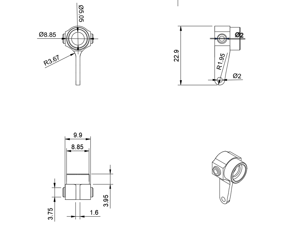 Front Knuckles
It serves the same purpose as the back knuckle, it supports the front wheel, however, the main difference between the front and the back knuckles, it's their size, the front is a little bit longer, to fit with the Ackeerman system bars.
Wheels
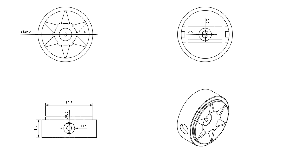 Wheels
We used four units of ths wheels, which were designed by us, taking care of every detail to achieve a unique aspect on Klevor's identity.
How does this drive system work?
This 4x4 transmission system consists of two metal differential, located on both axles. These differentials recieve movement through the main shaft, which passes through the 40-tooth pinion, which directly connects both differentials. This allows the generated torque by the motor to be evenly distributed between the front and real axles.
Connecting from each differential are the axle shafts, elements designed to transmit torque to the wheels. These axle shafts are coupled to the transmission cups located on the knuckle, which acts as a wheel support. This knuckle not only supports the wheels, but also allows it to rotate freely for traction and facilitates movement.
Thanks to this configuration, the system can move the whole assembly with just one motor, as the transmission and proper torque distribution through the differentials and axle shafts ensure that the wheels recieve the ecessary power.